Geometric tolerances for CNC parts
Geometric tolerances describe requirements for the form, orientation, location or run-out of part features. They complement dimensional information when function depends on surface geometry and the relationships between surfaces.
Form and the relationship between features
Flatness is an example of a form requirement. Parallelism and perpendicularity describe orientation relative to a datum, and position controls the location of a feature as specified on the drawing. Datums are indicated where the requirement calls for them.
Example
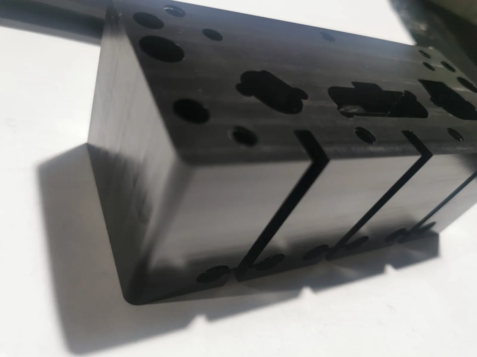
Flatness example
In a simplified example, a flatness tolerance of 0.02 mm requires the evaluated surface to lie between two parallel planes 0.02 mm apart. The value is not read as ±0.02 mm. The example is explanatory and does not represent a BSK manufacturing limit.
Datums must be clear
Datum surfaces or features must be identified on the drawing, together with their order where relevant. A photo of the part or an isolated dimension does not replace this information.
Standard and inspection
State the specification system and the standard used. ISO GPS and ASME GD&T should not automatically be treated as identical. For special requirements, include the edition and any clarifications needed for interpretation.
Specify which characteristics must be reported and in which condition the part is inspected. The method and acceptance conditions are discussed before the order is confirmed.
Geometric requirements on your drawing?
Send the documentation with the datums indicated.